

General Description
The cerebral exterior is the border between the subarachnoid CSF and neural
tissue, and should correspond to the pia mater. Thus, the cerebral exterior
separates brain from non-brain, cerebrum from cerebellum, and divides the brain
into its two hemispheres. The brain lobes are the four areas of cerebral exterior
including the frontal, parietal, temporal and occipital lobes. Each brain lobe
has distinct physiological functions. The brain lobe borders are distinguished
by specific sulcal and gyral borders.
Segmentation Procedure
The brain lobe borders are determined by drawing sulci lines in the sagittal
and axial views.
The insular cortex is hidden between the temporal and inferior parietal corticies. By drawing sulci lines in the sagittal view, we gain an outline of it in the coronal. Choose a sagittal slice where insula is clearly visible (Fig 1), then draw a circle around it (Fig 2). Do this for several slices and for both hemispheres.
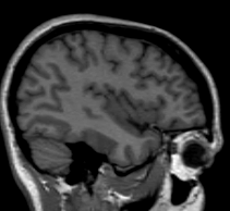
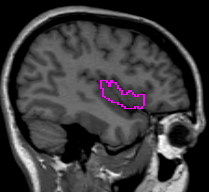
Figure 1 Figure
2
Once you have drawn your sulci lines, the insula should be clearly outlined (by little dots) in the coronal view (Fig 3). This is particularly useful in the more anterior slices.
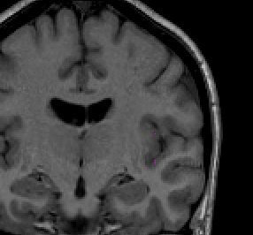
Figure 3
Because proper segmentation of the cerebral exterior includes a clearly drawn in Sylvian Fissure, segmentation of the insula in the more posterior coronal slices is simply a matter of extending these drawn in lines to the medial white matter (Fig 4-5)
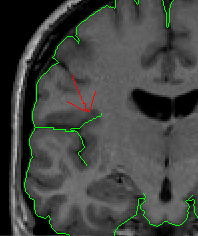
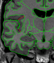
Figure 4 Figure
5
If insula has been the only structure segmented, but not labeled, then use the assign current label to all unlabeled outlines for all slices option in the Label tool. If not, individually assign each label.
Trace the Central Sulcus in the axial view. Drawing on several slices in the axial view is beneficial (Fig 6).
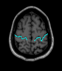
Figure 6
Trace the Central Sulcus in the sagittal view. Select a medial sagittal slice where the dots from the sulci lines drawn in the axial view are visible. Trace this sulcus inferiorly to the corpus collosum (Fig 7-8).
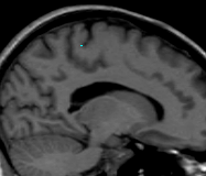
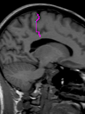
Figure 7 Figure
8
Trace the Sylvian Fissure in the sagittal view. Double click in the lateral sides of the coronal view to bring the sagittal view onto a proper slice. With the Sylvian Fissure visible, trace along it. Do this for both hemispheres (Fig 9).
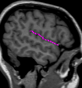
Figure 9
Step One: Beginning at the anterior most tip of the cortex and moving posteriorly, label all cortex as Frontal Lobe (while there is no insula present (Fig 10-11).
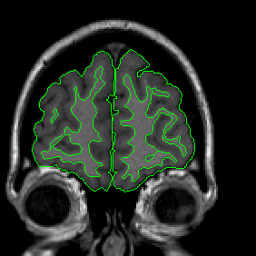

Figure 10 Figure
11
Step Two: When insula is present, but the temporal lobe has not yet connected with the frontal lobe, label all cortex surrounding it as Frontal Lobe. (Fig 12)
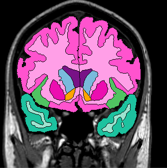
Figure 12
Step Three: When the Temporal Lobe connects with the Frontal Lobe draw a straight, horizontal line (in the coronal view) from the inferior tip of the insula to the medial frontotemporal junction (Fig 13). Extract the cortex that is between the inferior tip of the insula and this line (Fig 14). Do this for both hemispheres and label as Frontal Lobe. While there is no Central Sulcus present, label all cortex superior to the insula as Frontal Lobe.
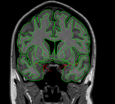
Figure 13
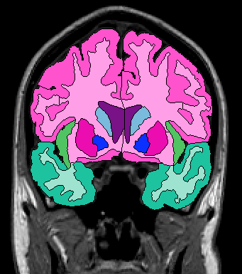
Figure 14
Step Four: When the Central Sulci lines drawn in the axial view appear in the coronal view (as dots) (Fig 15), connect the exterior at this sulcus with the white matter medial to it with a straight line (Fig 16). Extract the cortex superior to this and label it as Frontal Lobe (Fig 17).
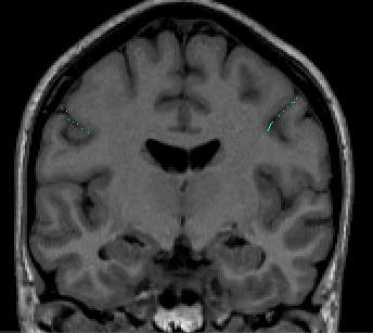
Figure 15
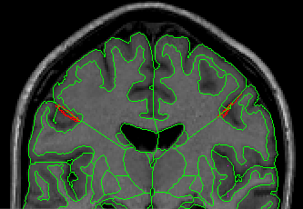
Figure 16
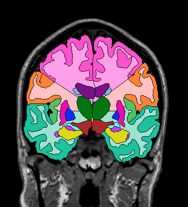
Figure 17
Step Five: When the Central Sulci lines drawn in the sagittal view appear in the coronal view (Fig 18), connect the exterior at this sulcus with the white matter lateral to it. Extract the cortex superior to this line and label it as Frontal Lobe (Fig 19). Stop extracting frontal lobe when the sulci dots disappear.
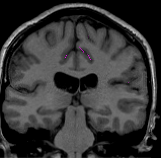

Figure 18 Figuure
19
Compute PON-TON midpoint. To compute this midpoint, double-click on the Temporal Occipital Notch (TON) (Fig 20) in the sagittal view and note what coronal slice results (Fig 21).
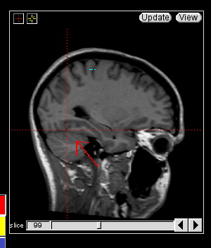
Figure 20

Figure 21
Next, double-click on the Parietal Occipital Notch (PON) in the sagittal view (Fig 22) and note what coronal slice results (Fig 23).
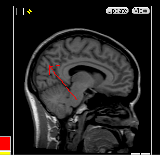
Figure 22
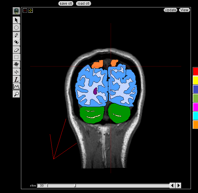
Figure 23
Combine the two coronal slice numbers and divide the result by two (if the result is not a whole number, then round up). Go to this slice number in the coronal view and note where the vertical crosshairs appear in the sagittal view. On the same sagittal slice that previous sulci lines had been drawn on Part 2 (here see Fig 9) draw a vertical line along this vertical crosshair (Fig 24). Do this for both hemispheres.
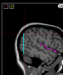
Figure 24
On the same sagittal slices, draw a horizontal line connecting the posterior end of the Sylvian fissure with the PON-TON line (Fig 25).
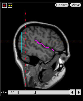
Figure 25
On the same sagittal slices that previous sulci lines had been drawn Part 2 (here see Fig 7-8), locate the cuneal point (Fig 26). The cuneal point is located at the intersection of the calcarine fissure and the parieto-occipital sulci. Double-click on this point in the sagittal view and draw a vertical line along the vertical crosshair that extends from the cuneal point to the cerebellum (Fig 27).
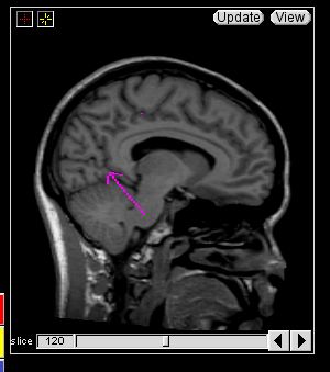
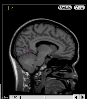
Figure 26 Figure
27
When the Temporal Lobe appears in the anterior, but is not yet connected with the frontal lobe, simply label it as Temporal Lobe (Fig 28).

Figure 28
When the Temporal Lobe first connects with the Frontal Lobe, there will already be a superior boundary drawn in for it from Frontal Lobe segmentation. Simply extract the temporal lobe and label it Temporal Lobe (Fig 29). The other boundary is already drawn in from Insula segmentation.
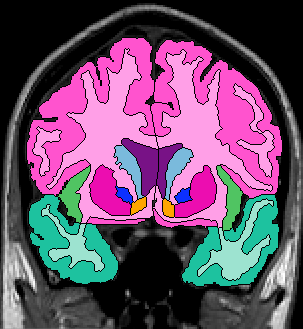
Figure 29
When the insula disappears, draw lines extending the Sylvian fissure to the medial white matter (Fig 30) and extract the cortex inferior to this line and label it Temporal Lobe. Do this for both hemispheres.
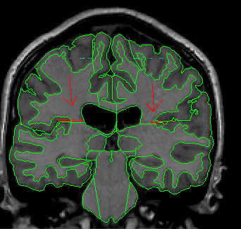
Figure 30
When the sulci lines that were drawn in Part 3 (here see Fig 27). are visible in the coronal as dots, the inferior medial section of cortex becomes occipital lobe, while the inferior lateral section remains temporal lobe. To set a boundary between the two, in the coronal view, locate the inferior lateral corner of the hemisphere (Fig 31). Draw a straight line from this point on the exterior to the white matter underneath it (Fig 32) Do this for both hemispheres.

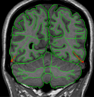
Figure 31 Figure
32
When the sulci lines that were drawn in Part 3 1.A (here see Fig 24). become visible on the coronal view (as one, long vertical line (Fig 33) the temporal lobe is no longer present.
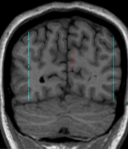
Figure 33
On the same medial sagittal slice that previous sulci lines had been drawn on, trace the paretial-occipital fissure (Fig 34).
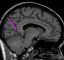
Figure 34
Borders drawn for previous segmentations are used as boundaries for the Parietal lobe.
In the anterior slices, the paretial lobe will appear between the temporal and frontal lobes (Fig 35-36) Simply extract this section of cortex and label it Parietal Lobe.

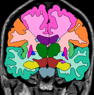
Figure 35 Figure
36
Moving to more posterior slices, parietal lobe will appear medially, inferior to frontal lobe, as well (Fig 37). Extract and label this section of cortex as Parietal Lobe.
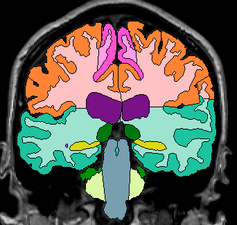
Figure 37
When the frontal lobe disappears, simply extract all cortex superior to temporal lobe (Fig 38) and label it Parietal Lobe.
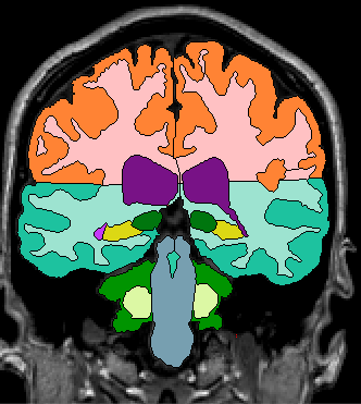
Figure 38
When the sulci lines that were drawn in the sagittal view to define the PON-TON line become visible in the coronal view (as one long line), the lateral portion of cortex has now become Occipital Lobe. The parietal lobes lateral boundary is now the intraparetial sulcus and a line should be drawn from the exterior superior to this sulcus to the white matter inferior to it (Fig 39). The parietal lobe at this point it simply the section of cortex between the intraparietal sulcus and the parietal-occipital sulcus. When this section of cortex disappears, there is no more parietal lobe.
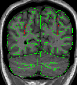
Figure 39
All boundaries have been established by segmentation of other lobes
The occipital lobe appears anteriorly once the sulci lines that were drawn in Part 3 (here see Fig 27) become visible in the coronal view. The section of cortex located medial to the temporal lobe and inferior to the parietal lobe is occipital lobe and should be extracted and labeled Occipital Lobe.
When the PON-TON line appears in the coronal view, all cortex inferior to parietal lobe is occipital lobe and should be extracted and labeled Occipital Lobe (Fig 40).

Figure 40
© 2007 Neuromorphometrics, Inc. All rights reserved.